
SOLID STATE RELAY
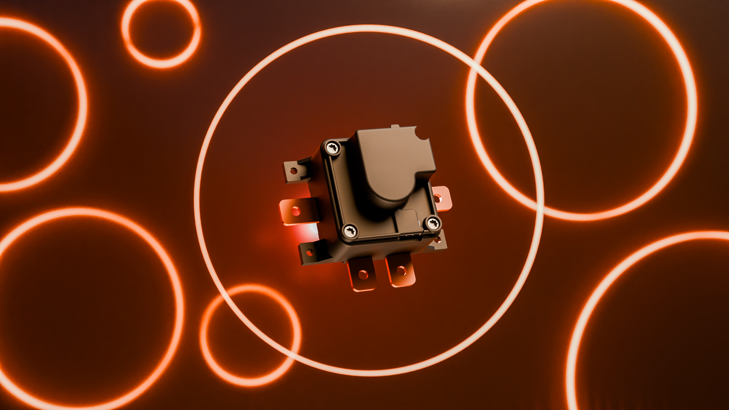
Semiconductor circuit breaker replacing mechanical contactors and pyrotechnic fuses in battery disconnection units. Microsecond fault interruption, zero arcing, unlimited switching cycles*.
SWITCHING DEVICES

*more than one million cycles are supported
AI animated Video

THE CHALLENGE
CONTACTORS AND FUSES ARE HOLDING YOU BACK
Battery disconnection units and power distribution equipment in electric vehicles, energy storage systems, and data centers rely on mechanical contactors, thermal fuses, and electromechanical breakers to interrupt high-voltage circuits. These components have fundamental limitations that become serious reliability and safety gaps in high-duty-cycle applications — and their trip behavior is fixed at the moment they're manufactured, not tunable once installed.
Commercial trucks switch thousands of times per year under extreme vibration and thermal cycling. Utility-scale storage installations operate for decades with frequent cycling. Data centers run some of the most expensive electrical loads of any industry, where unprotected fault current can destroy compute hardware in milliseconds. Across all three, contactor wear-out, single-use fuses, and millisecond-scale response times drive unplanned downtime and maintenance cost.

CONVENTIONAL BDU FAILURE CHAIN
MECHANICAL CONTACTOR
Opens in milliseconds under load
ELECTRIC ARC
EMI, ignition risk, contact erosion
MECHANICAL WEAR
Coil degradation, spring fatigue
DOWNTIME
Fuse replacement, service dispatch
THE SOLUTION
SEMICONDUCTOR SOLID-STATE SWITCHING
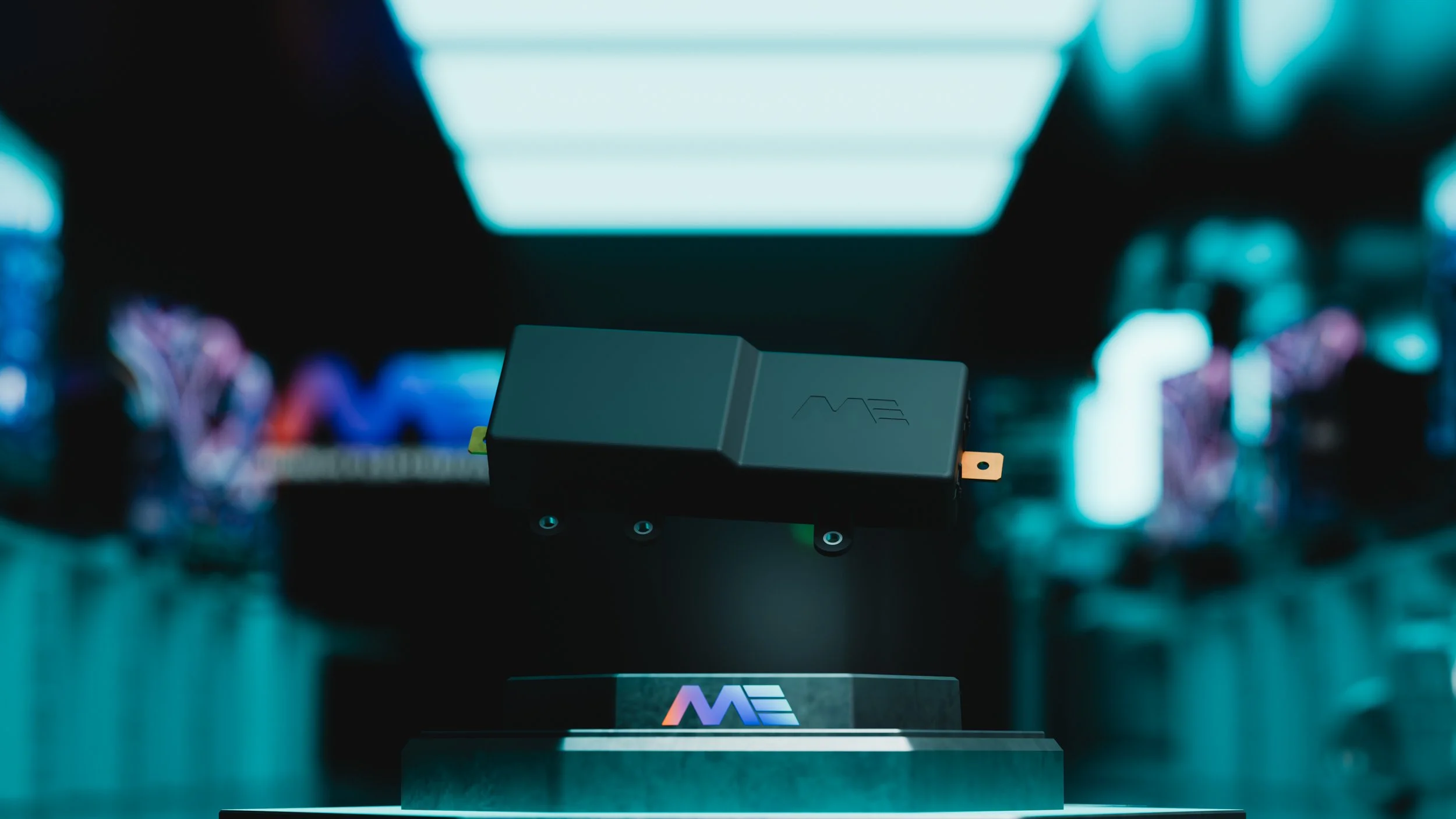
The ME Solid State Relay uses semiconductor switching elements on an high performance PCB, delivering microsecond fault interruption with no arcing, no mechanical wear, and no single-use components.
MICROSECOND SPEED
Self-triggered fault interruption in under 5 microseconds — three orders of magnitude faster than mechanical contactors. Limits fault energy and protects cells, busbars, and downstream electronics.
ZERO ARCING
No electric arc at any point in the switching cycle. Eliminates arc-related ignition risk in sealed battery compartments where thermal events may produce flammable gases.
FULLY RESETTABLE
Every trip is resettable. No pyro fuse replacement, no technician dispatch, no vehicle downtime. The SSR returns to service immediately after the fault condition clears.
SOFTWARE-CONFIGURABLE PROTECTION
The I²t trip curve is set in software, not baked into a physical fuse element — enabling precise coordination across multiple devices on the same network so a fault disconnects only the affected branch.
SEMICONDUCTOR POWER STAGE
Self-triggered short-circuit interruption in <5 µs

HIGH PERFORMANCE PCB
Embedded copper for high-current routing

BUSBAR HV INTERFACES
Direct mechanical integration into BDU

THERMAL INTERFACES
Compact thermal path, <100 W dissipation

PRODUCT LINE
TWO PRODUCT VARIANTS
A drop-in replacement for existing BDU designs, and an integrated module for new platform architectures.
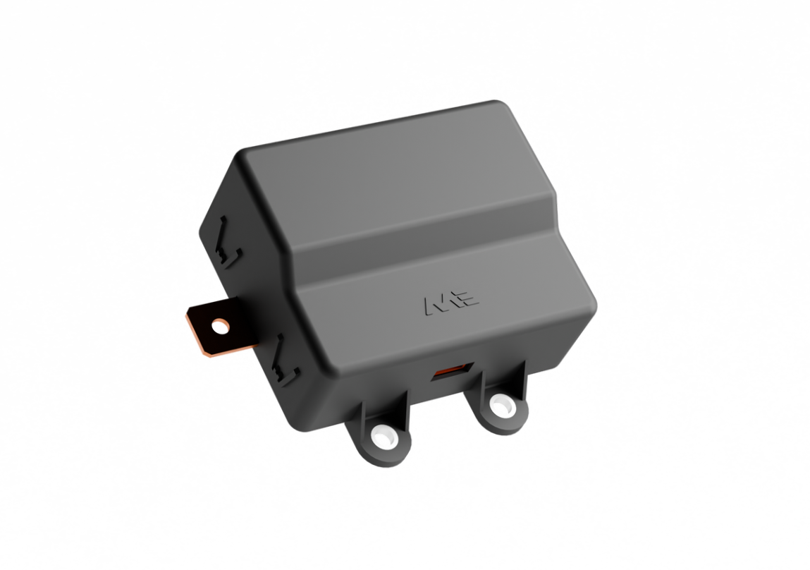
DROP-IN REPLACEMENT
ME SOLID-STATE RELAY

Stand-Alone SSR: Best for OEMs that want to upgrade switching performance and eliminate pyro fuses without redesigning the full BDU.
Semiconductor power switching
Self-triggered short-circuit protection
Busbar HV interfaces
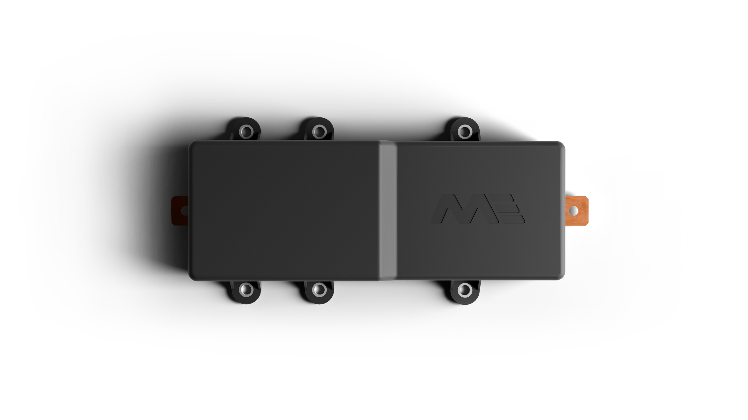
INTEGRATED MODULE

ME SOLID-STATE RELAY NEXT
Current-Sensing e-disconnect: Best for new platform designs or BDU consolidation projects where integrating sensing and switching into one module simplifies the system architecture.
Semiconductor power switching
Self-triggered short-circuit protection
Isolation monitoring
Voltage sensing
Current sensing (dual shunt)
Communication interface
Optional active pre-charge
Busbar HV interfaces
ADVANTAGES
KEY BENEFITS

SPEED
Sub-5 µs fault interruption — three orders of magnitude faster than mechanical contactors. Limits fault energy and protects cells from thermal damage during short circuits.

SAFETY
No electric arc at any switching point. Eliminates arc-related ignition risk in battery compartments with potential gas presence. Targets ASIL-C functional safety.

RELIABILTY
No contact erosion, no spring fatigue, no coil degradation. Solid-state switching eliminates wear-out mechanisms, especially under vibration and thermal cycling.

TOTAL COST OF OWNERSHIP
Higher unit cost offset by eliminating pyro fuse inventory, reducing service events, and extending system lifetime. Lowest cost for high-duty-cycle applications.
SOFTWARE ADVANTAGE
PROTECTION THAT’S SOFTWARE DEFINED
Unlike thermal fuses or electromechanical breakers, an SSR's protection behavior lives in software — configurable, self-testable, and instrumented for the life of the system.
CONFIGURABLE FAULT COORDINATION
The I²t trip curve is set in software, not fixed by a physical fuse element. Multiple SSRs connected in series can be coordinated precisely so they trip in the correct order — only the faulty section disconnects. In a data center, that's the difference between losing a rack and losing a row or the whole hall.

LATENT FAULT DETECTION
Thermal fuses and electromechanical breakers can fail closed on day one, and no one finds out until a real fault occurs and the device doesn't open. An SSR's protection function can be self-tested in software at any time, catching latent failures before they matter.
PREDICTIVE DIAGNOSTICS
Every switching event yields data — inrush current, voltage drop, continuous current, and more. Processed intelligently, this data flags components across the power network that are degrading and heading toward failure, enabling predictive maintenance that reduces downtime — typically the top KPI for data center operators.

MARKETS
APPLICATIONS
DATA CENTERS
The highest-value load in this list: rack-level compute hardware is worth far more than the switchgear protecting it. Software-configurable trip curves protect it from fault damage and coordinate selectively, so a fault clears at the rack — not the row or the hall.

HEAVY-DUTY ELECTRIC TRUCKS
High switching frequency, extreme vibration, and costly downtime make trucks a strong case for solid-state disconnection. Eliminates contactor wear-out and pyro fuse replacement across high-mileage commercial fleets.

COMMERCIAL VEHICLES
Buses, construction equipment, and delivery vehicles benefit from the same reliability advantages — fewer unplanned service events, simpler spare parts inventory, and safer operation in enclosed battery compartments.

BATTERY ENERGY STORAGE
Utility-scale and commercial storage installations cycle frequently and operate for decades. Unlimited switching lifetime and resettable protection reduce maintenance cost and improve availability over the full service life.
READY TO GO SOLID STATE?
A-samples are being built and lab testing is underway. Contact us to discuss technical requirements and sample availability for your platform.
AI animated Video
BATTERY MANAGMENT SYSTEMS MADE IN GERMANY
BISTA:
BI-STABLE RELAY
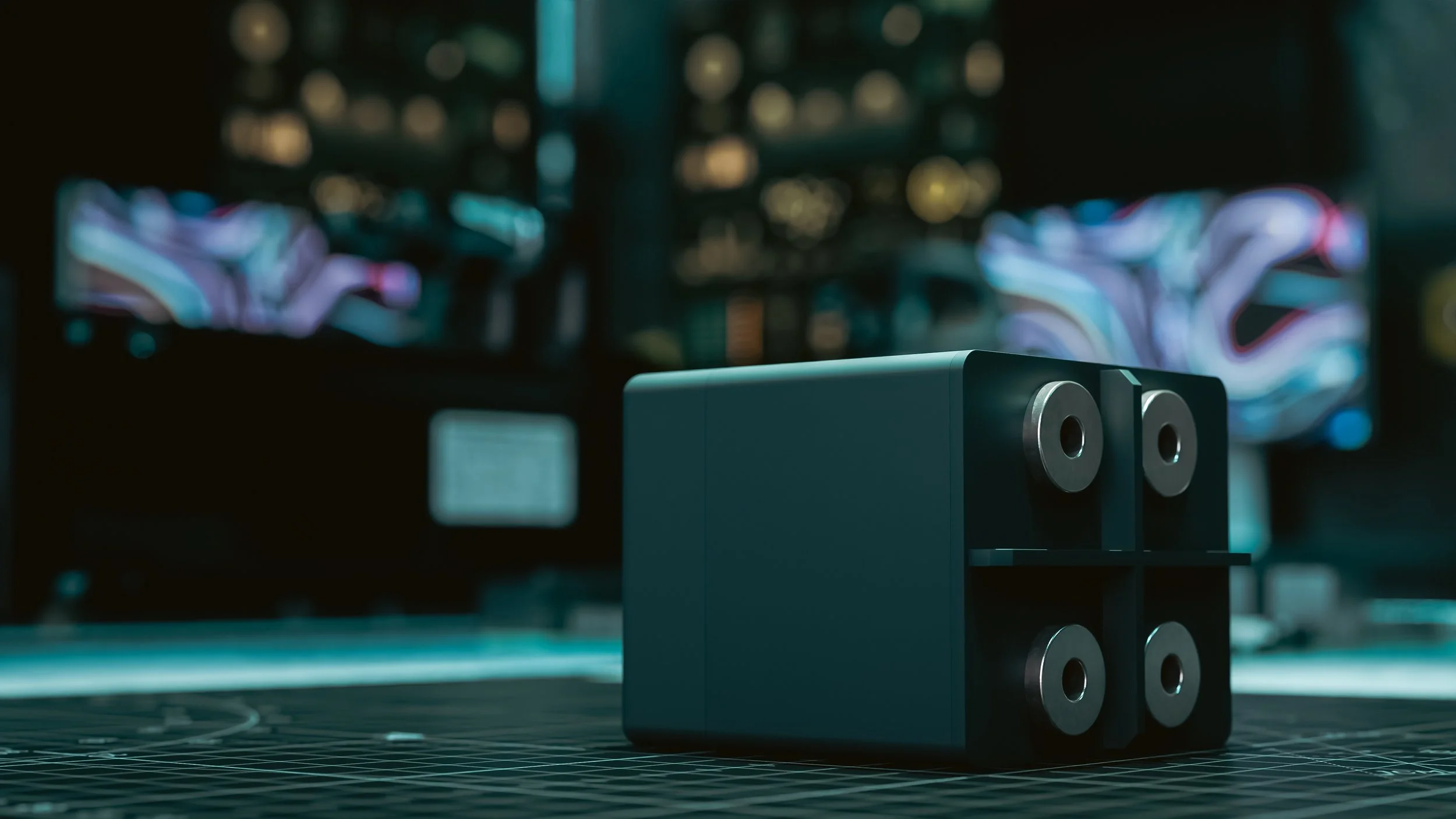
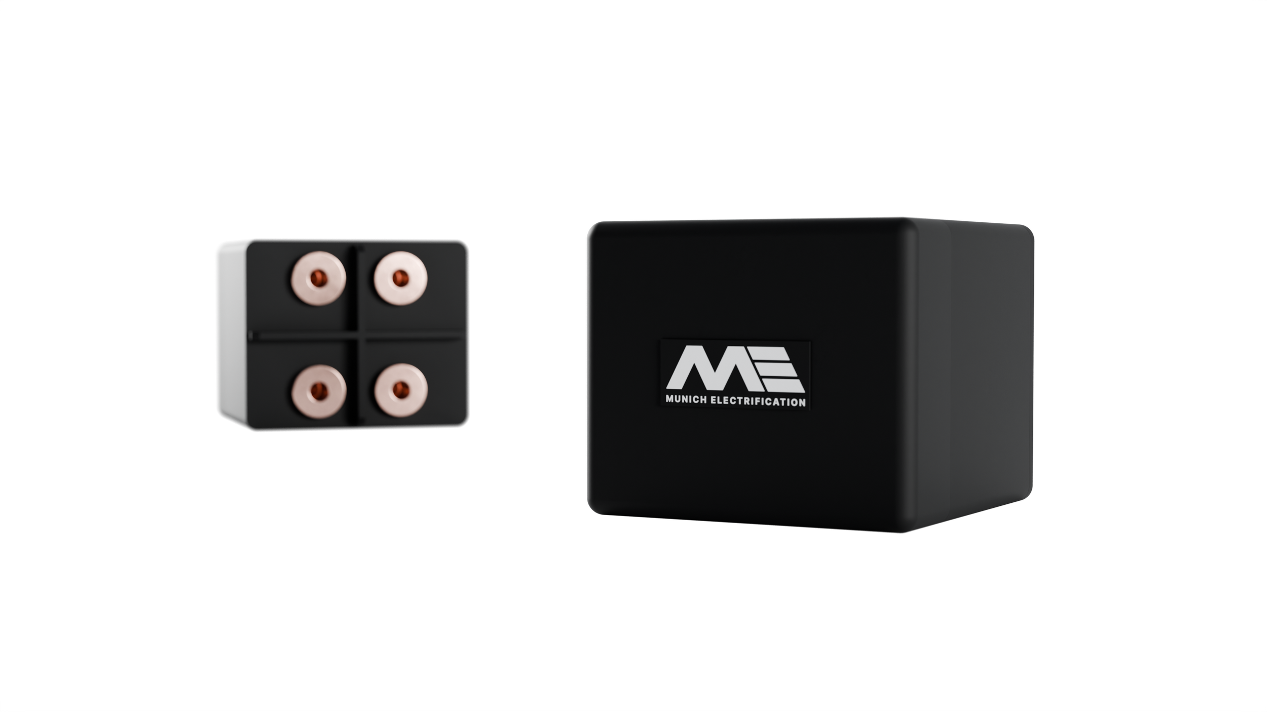
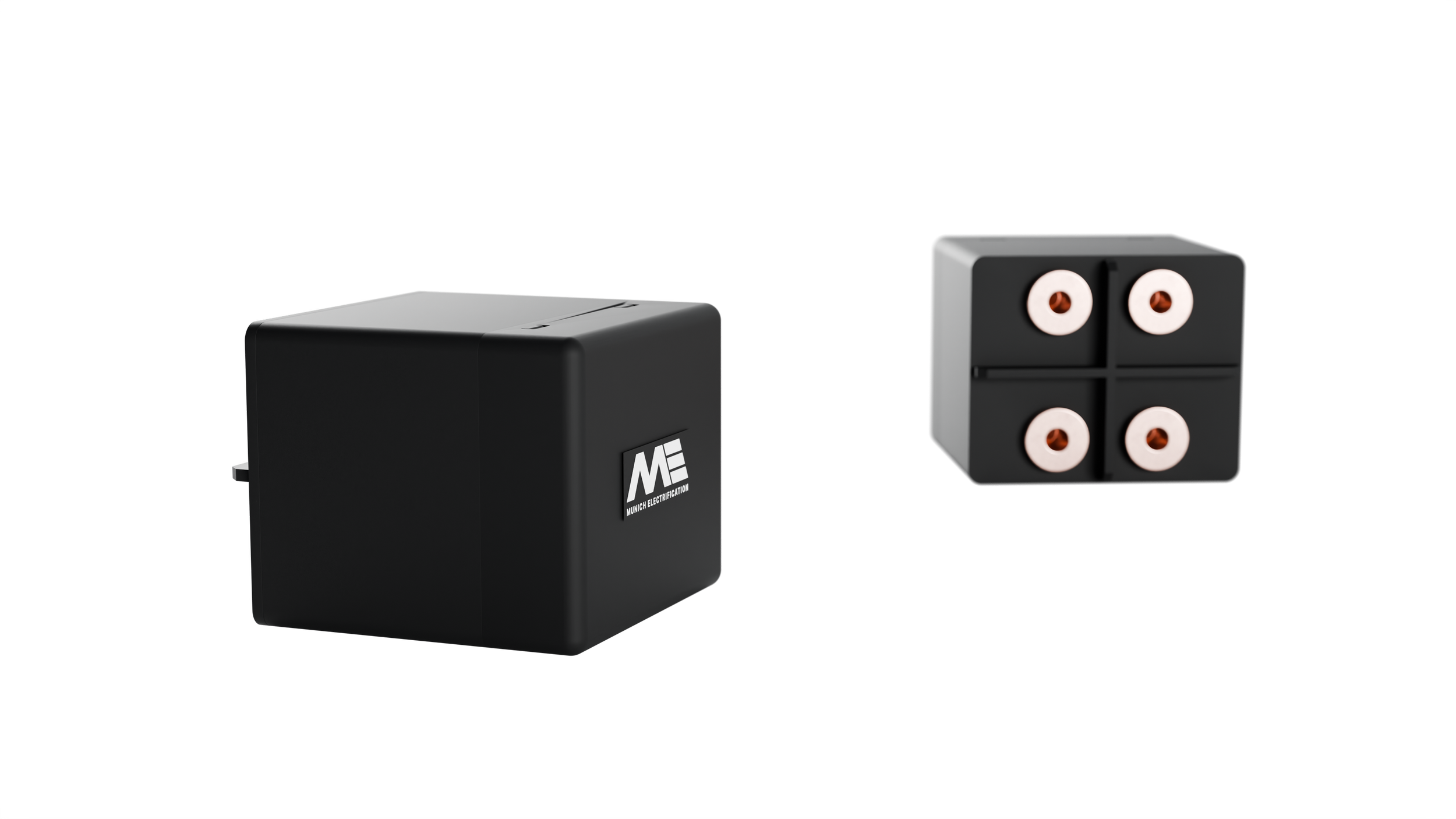
A HV dual pole bi-stable relay, engineered for applications up to 1000V. This relay presents a compact, light and cost effective replacement for two standard contactors.
BI-STABLE RELAY
PRODUCT OVERVIEW

COMPACT PACKAGING
Integrated double-pole, single-throw configuration designed for high-density power electronics.




BI-STABLE OPERATION
Bistable operation ensures current latched state regardless of loss of T30 + eliminates power consumption in both latched states.
HIGH-EFFICIENCY POWER PATH
High-grade silver-alloy contacts ensure low contact resistance and superior durability over the product lifetime.
INDEPENDENT GALVANIC ISOLATION
Optimized for architectures with a common main contactor, enabling safe, localized sub-system isolation.
SIMPLIFIED SYSTEM INTEGRATION
Operated via a single low-power GPIO, optimized to reduce complexity and costs.
KEY FEATURES
SWITCHING & CONTROL CONCEPT
MOTOR DRIVE MECHANISM
The contact bridge is driven by a motor actuated mechanical drivetrain.
No holding current required
Bi-stable actuator with optional position recognition
Simple 12V GPIO to drive motor, no dedicated contactor driver required
Optional position feedback signal
2 Pin control for both closed and opening state switching
ENGINEERING
OPERATING SPECIFICATIONS
| Parameter | Value |
|---|---|
| Configuration | Double Pole Single Throw (DPST) - BiStable - Motor Driven |
| Switching | Load-Free Only |
| Operating Voltage | 1000 V |
| Voltage Strength | 2500 V @ 4000 m Altitude |
| Max continuous Current | ≤ 500 A (dependent on Thermal Interface) |
| Resistance per Path | ~ 100 μΩ BoL |
| Electrical Control | 1x LV Input , 1x GND, 1x Feedback (optional) |
| Control Voltage | 12 V (9 V to 16 V Tested) |
| Control Current | < 1 A |
| Sealing | Unsealed |
| Switching time | < 400 ms - Closing, < 1200 ms - Opening/td> |
| Noise | ~ 80 dB |
| Dimensions | 60 x 50 x 65 mm |
READY FOR BISTA?
Contact us to discuss technical requirements and sample availability for your platform.
ME FLIPPER - 400V / 800V BATTERY CONFIGURATION SWITCH
Designed for passenger and light commercial vehicle applications, the Battery Configuration Switch delivers faster charging, simplifies the battery system and maximizes performance.
SWITCHING DEVICES
AI animated Video
ME FLIPPER –400 V/800 V BATTERY CONFIGURATION SWITCH
Intelligent power management company Eaton has partnered with Munich Electrification to develop and market its battery configuration switch (BCS), an advanced solution for 400-volt/800-volt dual string battery packs in electrified vehicles. This innovative, integrated, bi-stable device for parallel/series reconfiguration allows 800-volt vehicles to effectively charge via a 400-volt charger, while also offering numerous benefits compared to traditional solutions.
Designed for passenger and light commercial vehicle applications, the Battery Configuration Switch delivers faster charging, simplifies the battery system and maximizes performance.


HIGHLIGHTS IN A NUTSHELL:
Significant cost savings: The Flipper replaces three contactors and associated busbars and harnesses
Mechanical safety: Pack Short circuit due to crash, SW bug, or contactor malfunction inherently avoided
Stable conditions in loss of KL30C cases; no arching or bouncing possible regardless of all 12 V failure modes
Increased efficiency – no power consumed in coil during operation
Quicker startup time, since desired configuration is already in place
Minimal contact resistance due to reduction of contact points compared to conventional contactors
Improved reliability due to lower part count

ME DISCO LIGHT: DUAL-POLE HIGH VOLTAGE CONTACTOR
This disconnection device is a cost-efficient Dual Pole HV Contactor integrated into one compact housing for high voltage applications. It provides superior performance and packaging benefits due to its market-leading design.
SWITCHING DEVICES
ME DISCO LIGHT – DUAL-POLE HIGH VOLTAGE CONTACTOR
This disconnection device is a cost-efficient Dual Pole HV Contactor integrated into one compact housing for high voltage applications. It provides superior performance and packaging benefits due to its market-leading design.
